
1
/
of
1
Komatsu
Komatsu Crawler Dozers D375A-6 60001 and up Workshop Service Repair Manual
Komatsu Crawler Dozers D375A-6 60001 and up Workshop Service Repair Manual
Regular price
$16.99
Regular price
Sale price
$16.99
Shipping calculated at checkout.
Machine data plateRef 214762
- Brand
- Komatsu
- Equipment
- Construction
- Models covered
- Crawler Dozers
- Format
- PDF, searchable, print-ready
- Delivery
- Instant download after checkout
- Language
- English
Couldn't load pickup availability
What happens after you pay
- Download link opens on the order page immediately
- The same link is emailed to you — re-download any time
- Open on phone, tablet or PC; print only the pages you need
- Not sure it covers your serial range? Ask us before you buy
Original Illustrated Factory Workshop Service Manual for Komatsu Crawler Dozers D375.
Original factory manuals for Komatsu Loaders, Dozers, Excavators contains high quality images, circuit diagrams and instructions to help you to operate, maintenance and repair your truck. All Manuals Printable, contains Searchable Text and Navigation Bookmarks
Covered models:
D375A-6 60001 and up
Format: PDF, 1735 Pages
Language: English
Contents:
00 Index and Foreword
Table of contents
Table of contents
Foreword and general information
Safety notice
How to read the shop manual
Explanation of terms for maintenance standard
Handling of electric equipment and hydraulic components
Handling of connectors newly used for engines
How to read electric wire code
Precautions when carrying out work
Method of disassembling and connecting push-pull type coupler
Standard tightening torque table
List of Abbreviation
Conversion table
01 Specification
Specification and technical data
Specification drawing
Specifications
Weight table
Table of fuel, coolant and lubricants
10 Structure,function and maintenance standard
Engine and cooling system
Cooling system
Cooling fan pump
Cooling fan motor
Power train
Power train
Overall drawing of power train unit
Power train hydraulic equipment arrangement drawing
Damper and universal joint
Torque converter and PTO
Torque converter control valve
Main relief valve and torque converter relief valve
Lockup clutch ECMV and stator clutch ECMV
Scavenging pump
Transmission control
PCCS lever
Transmission
Transmission ECMV
Transmission lubricating oil relief valve
Steering and brake control
Transfer unit, bevel gear shaft and steering
Steering control valve
Steering clutch ECMV and Steering brake ECMV
Parking brake valve
Sudden stop prevention valve
Final drive
Undercarriage and frame
Track frame
Idler cushion
Track roller bogie
Main frame
Suspension
Hydraulic system
Work equipment hydraulic piping diagram
PPC control piping diagram
Work equipment control
Hydraulic tank
Accumulator
PPC lock valve
PPC valve
Piston valve
Quick drop valve
Pin puller switch
Pin puller solenoid valve
Blade control lever (only for the machine with dual tilt specification)
Work equipment pump
Control valve
Self-pressure reducing valve
Work equipment
Cylinder stay
Cab
Cab mount
Cab
Electrical system
Engine control
Engine control system
CRI engine control system
Monitor system
Machine monitor
Lamp system
Engine preheat (electrical intake air heater) control
Palm command control system
Sensor
Vehicle health monitoring system (VHMS)
ORBCOMM system
20 Standard value table
Standard service value table
Standard value table for engine
Standard value table for machine
30 Testing and adjusting
Tools for testing, adjusting, and troubleshooting
Diagnosis equipment list
Engine and cooling system
Testing engine speed
Testing intake air pressure (boost pressure)
Testing exhaust temperature
Testing exhaust gas color
Adjusting valve clearance
Measuring compression pressure
Testing blow-by pressure
Testing engine oil pressure
Testing EGR valve drive oil pressure
Handling of fuel system devices
Releasing residual pressure from fuel system
Testing fuel pressure
Handling of reduced cylinder mode operation
Handling of no injection cranking operation
Testing leakage from pressure limiter and return rate from injector
Bleeding air from fuel circuit
Testing fuel circuit for leakage
Replacing and adjusting alternator and air conditioner compressor belt
Measuring fan speed
Testing fan circuit oil pressure
Bleeding air from fan pump
Adjusting fuel control dial and decelerator pedal
Power train
Testing power train oil pressure
Adjusting transmission output speed sensor
Simple test procedure for brake performance
Adjusting brake pedal and parking brake lever
Adjusting position of pccs lever console
Emergency escape method when there is failure in power train
Undercarriage and frame
Inspecting wear of sprocket
Testing and adjusting track shoe tension
Hydraulic system
Measuring and adjusting work equipment oil pressure
Testing control circuit main pressure
Testing PPC valve output pressure
Adjusting play of PPC valve
Testing output pressure of ripper pin-puller solenoid valve
Checking location of cause of hydraulic drift of blade and ripper
Testing leakage inside work equipment cylinder
Releasing remaining pressure in work equipment cylinders
Bleeding air from work equipment cylinders
Adjusting ripper lever position
Work equipment
Adjusting work equipment lock lever
Adjusting blade
Cab and its attachments
Testing and adjusting operator's cab
Testing and adjusting operator's seat isolator
Electrial system
Special functions of machine monitor (EMMS)
Handling of voltage circuit of engine controller
Adjustment method when controller has been replaced
Preparation work for troubleshooting of electrical system
Inspection procedure of diode
Handling of optional devices
Request for opening ORBCOMM terminal
Initialization procedures for VHMS controller
Using method of KOMTRAX functions of ORBCOMM terminal
Precautions for replacing VHMS controller
Pm Clinic service
40 Troubleshooting
General Information on troubleshooting
Points to remember when troubleshooting
Sequence of events in troubleshooting
Checks before troubleshooting
Classification and procedures for troubleshooting
Failure codes table
Phenomena and troubleshooting numbers
Information in troubleshooting table
Troubleshooting method for disconnecting wiring harness of pressure sensor system
Connectors table and arrangement drawing
Connection table for connector pin numbers
T-branch box and T-branch adapter table
Fuse locations table
Troubleshooting by failure code
Troubleshooting of electrical system (E-mode)
Information contained in troubleshooting table
Troubleshooting of hydraulic and mechanical system (H-mode)
Information in troubleshooting table
List of Failure Modes and Causes
Troubleshooting of engine (S-mode)
Method of using troubleshooting chart
50 Disassembly and assembly
General information on disassembly and assembly
How to read this manual
Coating materials list
Special tools list
Sketches of special tools
Engine and cooling system
Removal and installation of fuel supply pump assembly
Removal and installation of fuel injector assembly
Removal and installation of cylinder head assembly
Removal and installation of radiator guard assembly
Removal and installation of cooling assembly (radiator, after cooler, and hydraulic oil cooler)
Removal and installation of radiator
Removal and installation of hydraulic oil cooler
Removal and installation of aftercooler
Removal and installation of engineassembly
Removal and installation of engine hood assembly
Removal and installation of engine front seal
Removal and installation of engine rear seal
Removal and installation of fan drive assembly
Removal and installation of fan motor assembly
Removal and installation of fuel tank assembly
Power train
Removal and installation of damper assembly
Disassembly and assembly of damper assembly
Removal and installation of power train unit assembly
Disconnection and connection of power train unit assembly
Disassembly and assembly of PTO assembly
Disassembly and assembly of torque converter assembly
Disassembly and assembly of TORQFLOW transmission assembly
Disassembly and assembly of steering case assembly
Removal and installation of power train pump and lubrication pump assembly
Removal and installation of scavenging pump assembly
Removal and installation of final drive assembly
Disassembly and assembly of final drive assembly
Undercarriage and frame
Removal and installation of track frame assembly
Removal and installation of idler assembly
Disassembly and assembly of idler assembly
Removal and installation of recoil spring assembly
Disassembly and assembly of recoilspring assembly
Removal and installation of track roller assembly
Disassembly and assembly of track roller assembly
Removal and installation of carrier roller assembly
Disassembly and assembly of carrier roller assembly
Removal and installation of bogie assembly
Disassembly and assembly of bogie assembly
Removal and installation of first bogie assembly
Separation and connection of track shoe assembly
Overall disassembly and assembly of track shoe
Link press press-fitting jig dimensions
Disassembly and assembly of one link assembly in the field
Disassembly and assembly of master link
Removal and installation of pivot shaft assembly
Removal and installation of equalizer bar
Disassembly and assembly of equalizer bar bushing
Removal and installation of segment tooth
Hydraulic system
Removal and installation of hydraulic tank assembly
Removal and installation of work equipment pump assembly
Removal and installation of fan pump assembly
Removal and installation of control valve assembly
Disassembly and assembly of control valve assembly
Disassembly and assembly of blade PPC valve assembly
Disassembly and assembly of ripper PPC valve assembly
Disassembly and assembly of hydraulic cylinder assembly
Disassembly and assembly of ripper pin puller cylinder assembly
Work equipment
Removal and installation of blade assembly
Disassembly and assembly of blade assembly
Disassembly and assembly of giant ripper assembly
Cab and its attachments
Removal and installation of ROPS guard
Removal and installation of operators cab assembly
Removal and installation of floor frame assembly
Removal and installation of air conditioner unit assembly
Removal and installation of operator's seat isolator
Disassembly and assembly of operator's seat isolator
Electrical system
Removal and installation of transmission controller assembly and steering controller assembly
Removal and installation of engine controller assembly
Removal and installation of VHMS controller assembly
Removal and installation of machine monitor assembly
60 Maintenance Standard
Engine and cooling system
Engine mount
Cooling fan pump
Cooling fan motor
Power train
Power train unit
Damper and universal joint
Torque converter and PTO
Main relief valve and torque converter relief valve
Lockup clutch ECMV and stator clutch ECMV
Scavenging pump
Transmission control
Transmission
Transmission lubricating oil relief valve
Power train and lubrication pump
Transfer, bevel gear shaft and steering unit
Steering control valve
Steering clutch ECMV and steering brake ECMV
Parking brake valve
Final drive
Sprocket
Undercarriage and frame
Track frame
Idler cushion
Idler
Track roller
Carrier roller
Track roller bogie
Track shoe
Main frame
Suspension
Hydraulic system
PPC valve
Hydraulic cylinder
Quick drop valve
Work equipment pump
Control valve
Self-pressure reducing valve
Work equipment
Cylinder stay
Blade
Cutting edge and end bit
Ripper
80 Appendix
Air Conditioner
Caution about refrigerant
Air conditioner component
Configuration and function of refrigeration cycle
Outline of refrigeration cycle
Air conditioner unit
Blower unit
FRESH/RECIRC air changeover damper
Compressor
Condenser
Receiver drier
Air conditioner control panel
Procedure for testing and troubleshooting
Circuit diagram and arrangement of connector pins
System diagram
Part and connector locations
Testing temperature control
Testing FRESH/RECIC air changeover
Testing relay
Troubleshooting chart 1
Troubleshooting chart 2
Information in troubleshooting table
Troubleshooting for power supply system (Air conditioner does not operate)
Troubleshooting for compressor system (Air is not cooled)
Troubleshooting for blower motor system (Air does not comeout or air flow is abnormal)
Troubleshooting for temperature control
Troubleshooting for FRESH/RECIRC air changeover
Troubleshooting with gauge pressure
Connection of service tool
Precautions for disconnecting and connecting
Handling of compressor oil
90 Diagrams and Drawings
Hydraulic diagrams and drawings
Symbols used in hydraulic circuit diagrams
Power train hydraulic circuit diagram
Hydraulic circuit diagram
Electrical diagrams and drawings
Symbols use in electric circuit diagrams
Electrical circuit diagram
Index
Delivery & file format
Delivery & file format
This is a digital PDF download, not a printed book. After payment the download link appears on your order confirmation page and is emailed to the address you entered. Files open in any PDF reader on phone, tablet or computer and can be printed.
Check the serial range before you buy
Check the serial range before you buy
Manufacturers change procedures and part numbers by serial-number break. If your data plate shows a serial prefix that is not listed above, contact us with the model and serial number and we will confirm coverage before you order.
Share

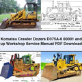
Komatsu Crawler Dozers D375A-6 60001 and up Workshop Service Repair Manual
Komatsu · Construction · PDF · Instant download
$16.99
- Instant download PDF link on your order page and by email right after payment.
- Secure checkout Encrypted Shopify checkout — we never see your card.
- Print-ready PDF Searchable text, print the pages you need for the workshop.
- Phone, tablet, PC Open it in the cab, the workshop or the office.
